Hardware tessellation as we know it today (Dx11-style) had its origins on the Xbox 360, which released in 2005. Time flies, right? It was a natural step in the evolution toward film-quality realtime rendering. After all, tessellation was a key component of the original Pixar Reyes paper [7].
Now that it’s 20+ years later, we have more experience with the algorithm, and hardware tessellation has not become the solution for these use cases. But the core ideas in Dx11-style tessellation are still good ones, and they’re worth revisiting on their own terms. With the benefit of hindsight, we can take those ideas, make different decisions along the way, and see if we can land on an algorithm that satisfies the same constraints with some more desirable properties.
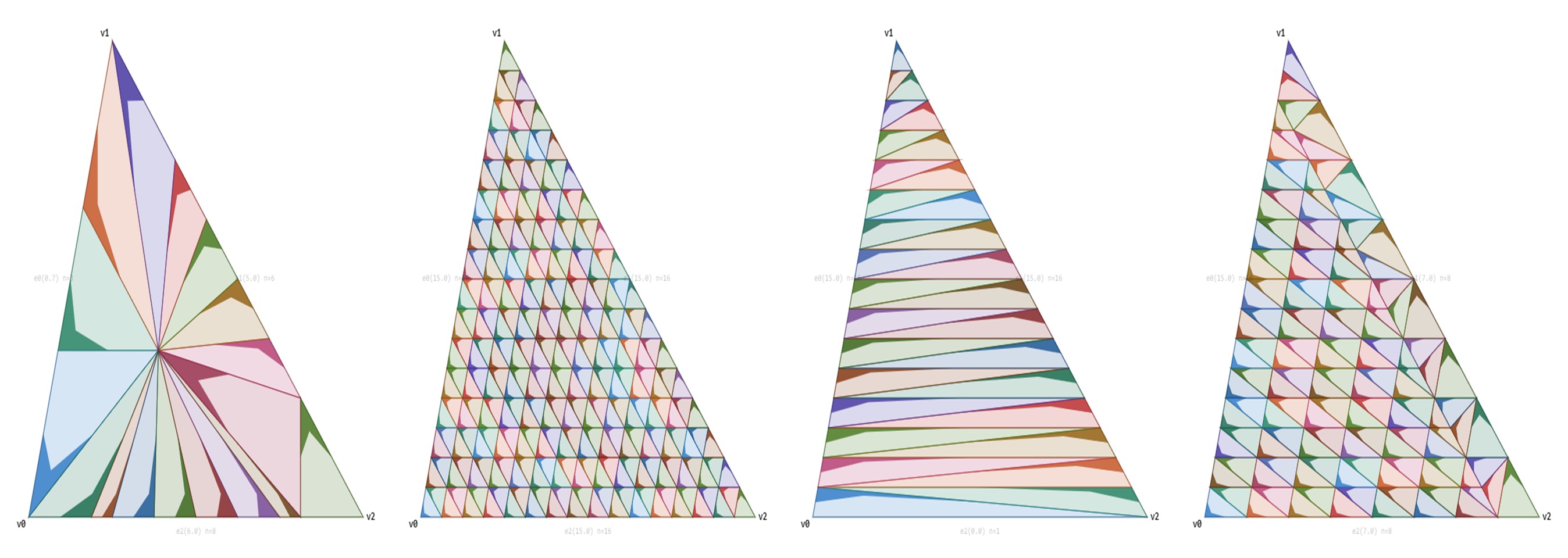
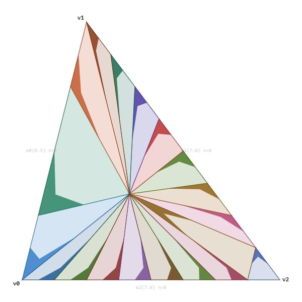
The final algorithm, once we get there, is going to look like this. It allows us to transition among all the patterns in the header image without popping.
The code is stored as JavaScript, so feel free to use it as you wish (it’s MIT licensed). I essentially took my existing C++ code and said “Mr. Claude, turn this into a JavaScript viewer, GLHF.”
How does Dx11 tessellation work, exactly?
Each edge of a triangle has a tessellation factor that roughly describes how many segments the edge has. In the case of Dx11, this value is in the range [1,64]. The key design decision is that each tess factor is a float value, and we can lerp between any values without a visible pop. From that perspective, we can split tessellation into two subproblems.
- Given a tessellation factor, split the edge into line segments.
- Given those edge line segments, split the interior of the triangle.
There are overviews online [3][4][5], as well as Fabian Giesen’s writeup of the Dx11 tessellator stage [6]. But for this exercise, we’re going to dive into the nitty-gritty details, and derive them as we go.
How should we tessellate a line segment? The most obvious solution would be to use subdivision, splitting each edge in half at each power of two.
Note: Tess factors in Dx11 are from [1,64], but I’ll be using ranges starting at 0 to simplify the formulas.
This gives us an ideal tessellation level at each power of two. Tess factors of 8 and 16 look great, but how should we handle a value of 11? Instead of going straight from 8 to 16, we can add those points one at a time. Conceptually, if we want a value of, say 11, we can think of the last added point as a “pivot”. At a tess factor of 11, 8 should be taken by the previous power of two, 3 of those new slots should be taken, and 5 are remaining. You can derive the formula yourself (or look at the code) but the results look like this:
That uses the same points as raw subdivision, but transitions them one at a time instead of introducing all of them at a power of two. But how could we modify the algorithm to have a clean transition without pops? All points stay the same, except the pivot point. For a value of 10.3, we round up to 11 segments. 8 points are locked from the previous subdivision, 2 points have already transitioned in, and the last point has a 30% lerp from the previous point and where it is going to.
Now it’s getting more interesting, and the next problem is the distribution. We want an evenly spaced tessellation, but in our current iteration we have dense spacing below the pivot and sparse spacing above it. Dx11 solves this problem by making all points the same length except the one that is sliding in.
This change is both good and bad. The good news is that we get a more evenly spaced tessellation. The bad news is that it introduces a lot of movement. Before, only the pivot point was moving. But now, all points are moving all the time.
We have one more practical problem: Symmetry. If we have two triangles next to each other, cracks will form if the tessellation is moving in opposite directions. Fortunately, we can fix this by mirroring the tessellation across the bottom. And that gives our Dx11 result.
This is, AFAICT, the algorithm for fractional even tessellation in Dx11. We have solved the first problem (given three tess factors, split the edges). Now we need to find an algorithm that splits a triangle internally according to these tess factors, without causing popping.
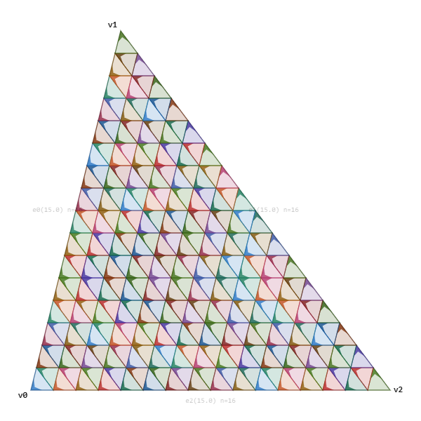
As a first step, let’s start with our original triangle, and split it into 6 smaller triangles.
Using the internal tess factor, we can create a tessellated triangle using regular “triforce” tessellation. This gives us 6 tessellated triangle regions.
The obvious problem is that now all 3 edges have the exact same tess factor. We can solve that by simply discarding the outermost strip of triangles.
All we have to do now is connect the internal tessellation to our edge tessellation, without actually causing a pop. The trick is that we should think in terms of the original powers of two. Let’s show a line down the middle which is the smallest power of two greater than or equal to the two tess factors. Then let’s match the lhs and rhs sides to the middle. The lhs tess factor here is the internal tessellation and the rhs tess factor is the edge tessellation on the other side of the gap.
Then we can match from lhs to rhs, noting that multiple points of lhs might point to the same rhs point. For each point on the right, we can find its reverse match by walking back and connecting to the lhs points.
To fill the gap with triangles, for each lhs point, we can find the current and next rhs match. Then add a triangle fan to connect to rhs, and then add one extra reversed triangle to fill it in. But note that we will want to skip the very last triangle. The blue triangles show the triangle fan from the current rhs match to the next rhs match. Then the red triangle closes the strip.
And finally, we can use this matching algorithm to fill in the gaps for all 6 triangles.
The Good and the Bad
This algorithm has several very interesting properties. The primary advantage of this approach is the flexibility. We can choose any function for calculating tess factors for an edge, and then the tessellation just works. And since the transition is continuous, we never have to pop.
On the other side, this flexibility results in less-than-ideal patterns. So we’ll go through them and how we can improve them with the clamped parallelogram approach.
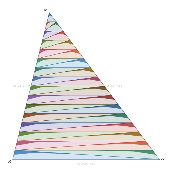
Varied Tess Factors: Suppose that we have two edges with a high tess factor and one with a low tess factor. This is quite common with thin triangles. Ideally we would like a tessellation pattern that can directly connect the left and right side together. But since we only have a single internal tess factor, it will either be under-tessellated or over-tessellated.
Instead, we can solve this problem by making a tess pattern that allows us to directly connect between the two high tess-factor edges.
Inefficient Patterns: By splitting the triangle into 6 similar triangle regions we use more triangles than we need.
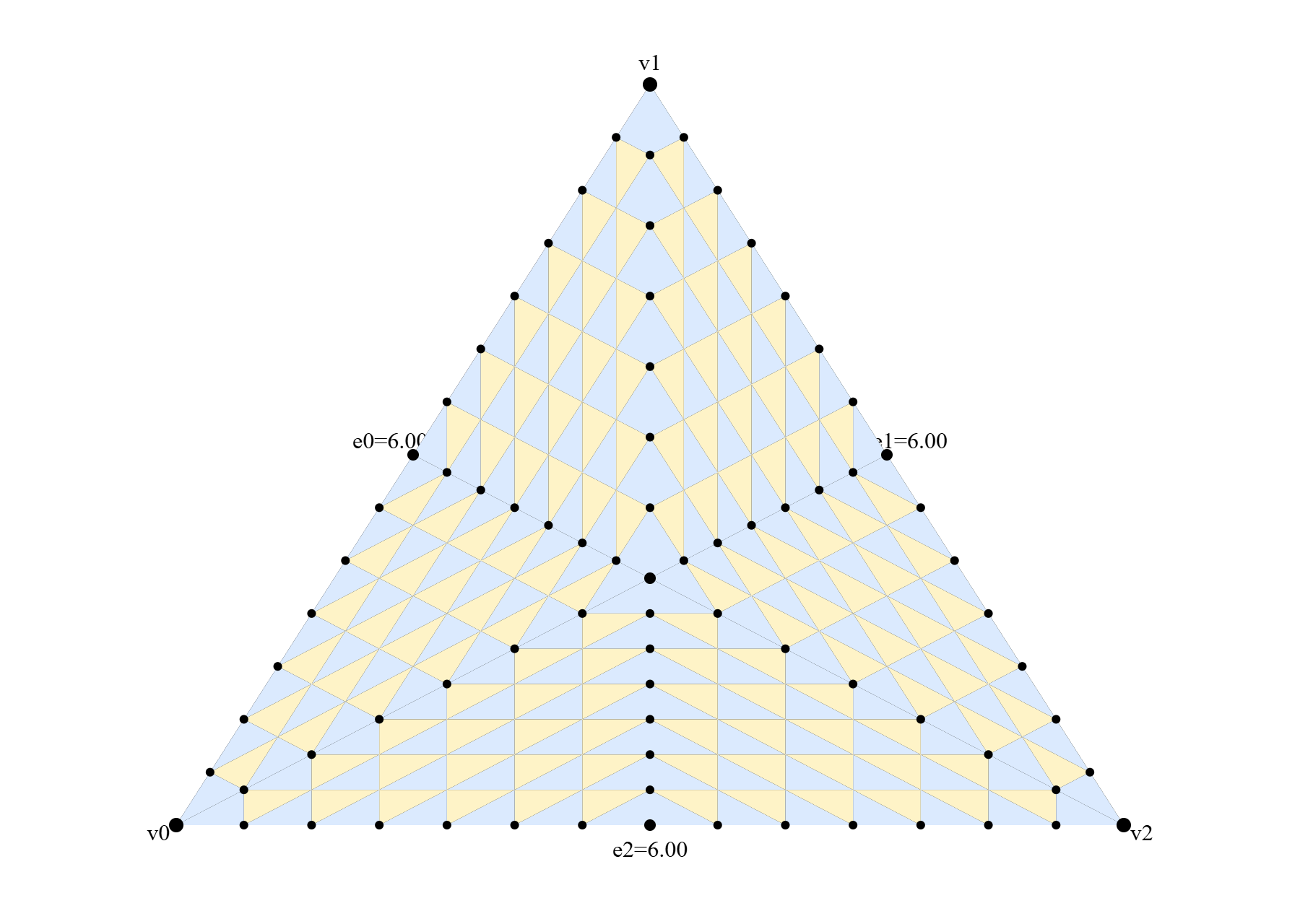
In contrast, with the clamped parallelogram approach, any time all three tess factors are the same, it will be topologically equivalent to triforce tessellation. Although the spacing may be uneven, which is necessary to allow lerping tess factors without pops.
Bending: If we are using tessellation for deformation (which is one of the most compelling uses of tessellation) we generally want to maintain straight edge loops to avoid sharp bends in the resulting tessellated mesh. If the original mesh was quads, we would want clean edge loops from left to right. Note that theoretically we could use the Dx11 quad primitive tessellation, but that opens a whole new set of issues with mixed triangle/quad meshes which are quite common (i.e. Suzanne from Blender).

Instead, the clamped parallelogram pattern makes regular quads with clean edge loops that degrade gracefully as the tess factors deviate from each other.
Minimum triangles: Fractional even has a minimum tessellation of 6 triangles, causing a sudden jump in cost by just “turning it on”.
On the other side, clamped parallelogram tessellation can transition all the way from a single triangle.
Movement: The Dx11 pattern is very “bouncy”. When this is used for actual displacement mapping, sharp edges cause visible back and forth wobbling as the tess factors move. The new function is significantly more stable at the expense of more unequal distribution.
For simplicity, I’m focusing on fractional even. We can avoid the minimum triangles issue by using fractional odd, but that would greatly increase the amount of movement, while leaving the bending and inefficient patterns unchanged. While I don’t have an implementation of fractional odd tessellation, the algorithm essentially removes the midpoint of each edge, and any point that would have “slid out” from the midpoint now “slides in” from the outside.
Tessellating a Line
But before we try to improve the actual pattern, let’s revisit tessellating a line. The algorithm in Dx11 makes the spacing even except for the one sliding in. It sounds beneficial in theory, but the movement causes practical issues.
The first thing we are going to do is actually take a step backwards. We’ll revert to the previous subdivision algorithm, where we add points one at a time and lerp the new point in. Here is a comparison of the two. You can really feel the amount of “bouncy” movement.
As an interesting note, Dx11 tessellation does not converge. In particular, look at the path of the middle point. At a tessellation value of 4, the midpoint is 0.5. But as we tessellate, the next two points slide in below pushing the midpoint to 0.6667. Then the next two points slide in above that point which pushes it back down to 0.5 by the time we have 8 points. During each transition from one power of two to the next, this middle point goes from 0.5 to 0.667 and back to 0.5, never converging. The graph below shows the tess pattern as it lerps over the range.
Here is the reverted version. Despite the poorer distribution of points, the stability is worth it. This is our new starting point.
Let’s take a different approach. Instead of adding in points one at a time, let’s insert all the odd points before adding any of the even points. The distribution of edge sizes is the same, but the large and small edges are more evenly balanced.
To further improve this, we can split the higher tessellations into blocks. When we go from, say, 64 to 128, new points will be added so quickly that they will look like popping even though it’s technically continuous. The solution is to divide our region into blocks, so that each power of two has 4 regions of different topology. We have multiple points sliding simultaneously, but the motions are slower and less likely to have a sudden movement that “feels” like a pop.
As a final tweak, we want to have a clean transition from a tess factor of a plain line segment to the initial tess factor. When we transition from a tess factor of 1 to 2, fractional even simply clamps you to a minimum tess factor of 2. Instead, we can slide in from both endpoints meeting at the midpoint. You can see it by dragging the slider below between 1.0 and 2.0.
And that is the final line tessellation algorithm. Next, we will focus on the internal triangle tessellation pattern.
The Gap and the Clamped Parallelogram
How should we actually tessellate the triangle? I spent a lot of time on this problem, and the solution I eventually landed on was a clamped parallelogram. Let’s start with a vanilla parallelogram using the tess factors of the bottom and left edge. For each point in the parallelogram, the barycentric coordinate is:
float u = EdgeT(i, n0);
float v = EdgeT(j, n2);
It actually looks pretty good. The distribution is straight. You can’t get much straighter than a parallelogram! But a parallelogram is not a triangle. Fortunately, there is a simple way to turn this parallelogram into a triangle: Clamp it.
float u = EdgeT(i, n0);
float v = EdgeT(j, n2);
u = min(u, 1 - v);
Now we get a very straight pattern, and it’s a triangle (progress!) but the left and right side are constrained to be the same. We need to modify this algorithm to allow the left and right edges to have different tess factors.
Fortunately, we can use the same trick as Dx11: Skip the gap and match it separately. We can determine the gap as the maximum of the left and bottom edge gaps and adjust the clamping line.
float u = EdgeT(i, n0);
float v = EdgeT(j, n2);
u = min(u, 1 - (gap + v));
How should we match the gap? It’s actually quite simple. We can match from the lhs to rhs, using roughly the same algorithm as before. Except, instead of mirroring the top and bottom, we need slightly different versions. The key insight is that as the tessellation factors increase, new points slide out of the middle. For the lower half, this means new points will come from above, and for the upper half, new points will come from below. Note that when matching from lhs to rhs, we always want the first triangle to go up the rhs side so that we can create triforce tessellation.
And finally, here is that same matching pattern converted to triangles.
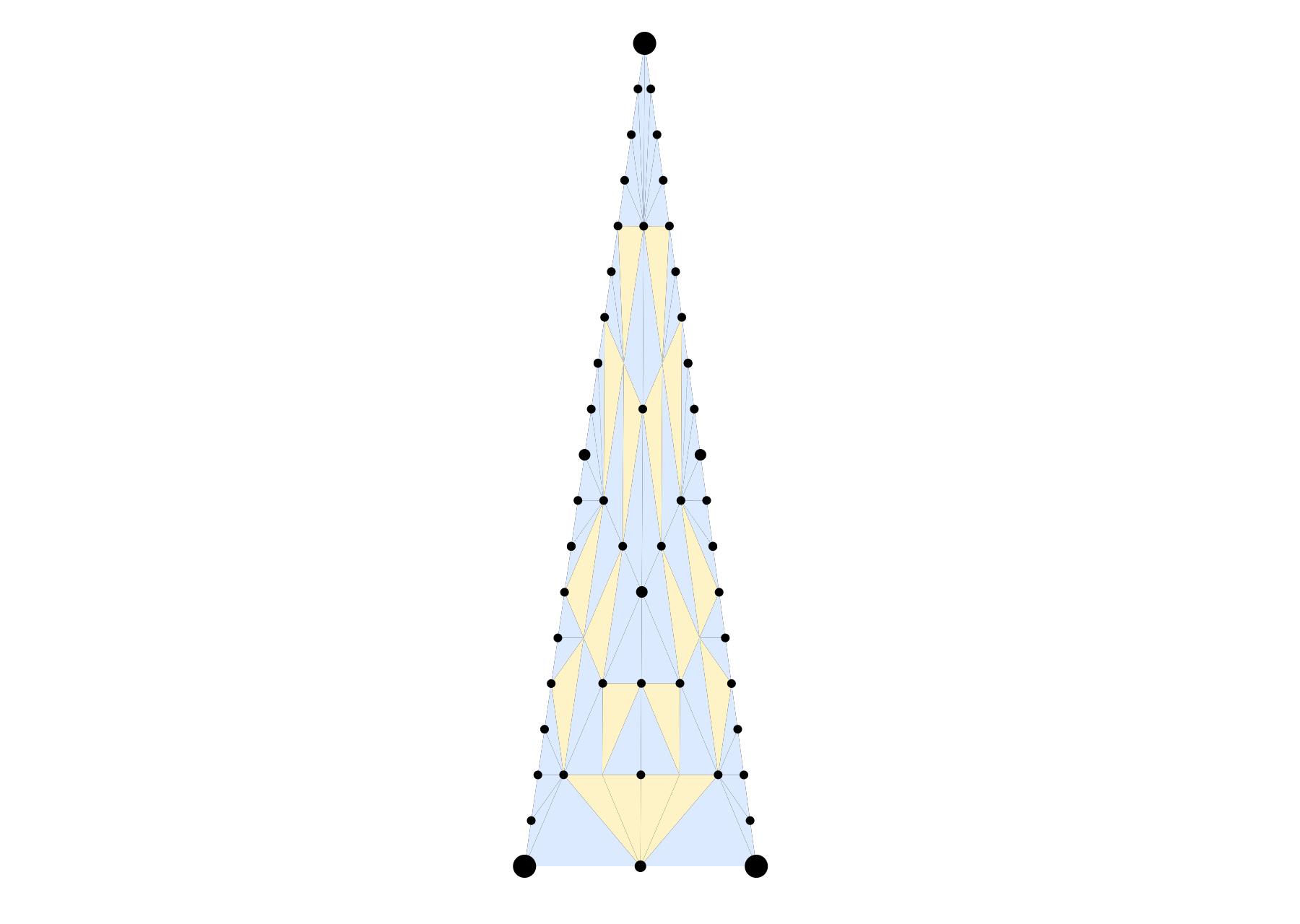
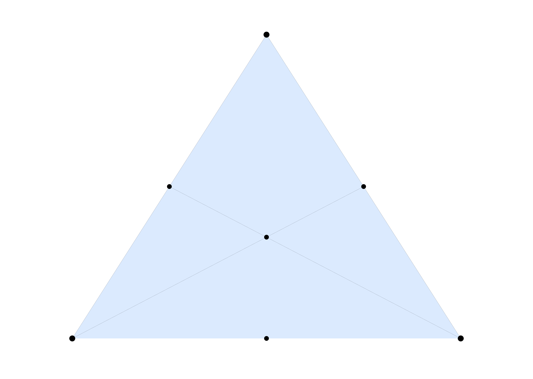
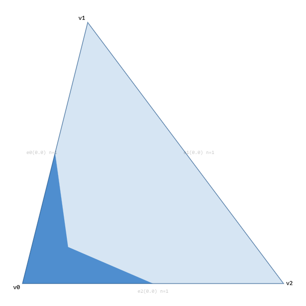
One final detail: We need to handle the transition between a plain triangle and this new pattern. I found the easiest method was to have an internal point start at v2. Then as the tess factors increase, this point slides over to the midpoint of v0/v1. During this transition, the pattern is essentially a triangle fan, except for that one triangle at v2. The triangle at v2 must not touch the centroid point so that it can transition seamlessly into triforce tessellation.
Thus we have three “types” of triangles. Type 0 is just a triangle. Type 1 is the triangle fan, and Type 2 is the full tessellation algorithm.
As a sidenote, we should mention the order of the indices. Since this algorithm is targeted for WebGPU, SV_PrimitiveID support isn’t guaranteed and Mesh shaders are not viable, so we need a consistent provoking vertex. This does mean we have to double up our internal points, but vertices on both sides of the gap are only used once. In the diagram, the darker edge is the provoking vertex.
And that gives us the final algorithm:
Quads and Edge Loops
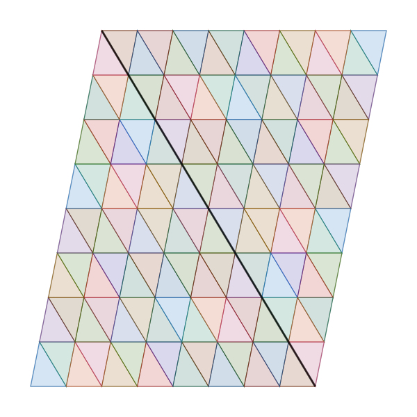
We can also make a special case for quads. When a source primitive is a quad, we need to split it into two triangles. Then we can choose the tess factors for all three sides of each triangle and tessellate them as we wish. However, if we know that the source is a quad, we can instead cheat so that the diagonal uses the same tess factor as one of the two edges. In this case, the diagonal tess factor is forced to the edge on the left.
Since the diagonal and left edge are the same tess factor, the horizontal edge loops remain straight. Most horizontal lines stay straight through the diagonal, and the vertical lines are mostly straight as well.
Rotational Symmetry
One property of Dx11 tessellation that we actually lose is rotational symmetry. With Dx11, you can switch your triangles from v0/v1/v2 to v1/v2/v0 and the pattern will look identical. However, we lose that property, as the clamped parallelogram is always along the v0/v1 and v0/v2 edges, with the gap always along v1/v2. The simplest approach is to always try to ensure that the smallest edge is v0/v2.
Implementation
The two interactive viewers used throughout this post are self-contained HTML pages. You can open them directly, look at them, change them, do what you want. The code is permissively licensed under MIT.
tess_visualizer.html: Line tessellation modes and fractional even viewer.
tess_patch_v18.html: Clamped parallelogram viewer and matching modes.
Lines: To simplify the line algorithm, we can split the ranges into “tokens”. Even though the tess factor can go from [1,256], we can split that into 25 specific ranges, called tokens. The float tess factor becomes a token id and a lerp factor. Then for every token, we can store the start and end values of each point in a table. It packs quite well, since the start and end point can fit in a single byte. The entire table fits under 4k.
Interior Rows: For the interior triangles, if we directly clamped the parallelogram we would have over half degenerate triangles. So for each pair of tokens for e0/e2, we can determine the smallest possible gap values, and determine the maximum number of columns that each row could have. Then this can be stored in a table, where for each row, we store the maximum number of columns and the prefix sum.
Reverse Lookup: For the gap, given each pair of e0 and e1, we can just precalculate the topology. The topology is created by walking up the gap, and adding the new triangle on the left or the right. Theoretically, we could store it as one bit per triangle. However, we want to have a reverse lookup. Instead we can pack the information for 16 triangles into 32 bits. The first 16 bits store the number of triangles on one of the sides, and the other 16 bits store the bitmask for this sequence. Then for each triangle, we can extract the lower index on lhs, the lower index on rhs, and whether the next vertex is on the left or the right.
// One entry per (token1 * NT + token0) pair. NT = 25.
struct GapInfo {
    uint16_t m_gapStart;             // offset into m_gapData (u32-strided)
    uint16_t m_gapPrims;             // strip length = n0 + n1 - 1
    uint16_t m_rhsPrimLookupStart;
    uint16_t m_rhsPrimLookupNum;     // = n1
    uint16_t m_lhsPrimLookupStart;
    uint16_t m_lhsPrimLookupNum;     // = n0 - 1
    int8_t   m_lhsLastPrim;
};
extern GapInfo  g_gapInfo[NT * NT];
extern uint32_t g_gapData[];         // packed: hi16 = prefix sum, lo16 = bitmap

struct MatchData {
    uint16_t numBelowRhs;            // # RHS-advancing prims strictly below `prim`
    uint16_t numBelowLhs;            // # LHS-advancing prims strictly below `prim`
    bool     isRhs;                  // true  => new point on the RIGHT
                                     // false => new point on the LEFT
};

// O(1): one u32 load, two bit ops, one popcount.
MatchData LookupMatchData(Token tok0, Token tok1, uint32_t prim)
{
    const GapInfo& gi = g_gapInfo[tok1.m_table * NT + tok0.m_table];

    // 16 prim bits per u32 word.
    uint32_t word = g_gapData[gi.m_gapStart + (prim >> 4)];
    uint32_t bit  = prim & 0xF;

    uint32_t bitmap = word & 0xFFFFu;       // 1 = RHS-advancing prim
    uint32_t prefix = word >> 16;           // # RHS prims in earlier words

    // Bit 0 = first prim in this 16-prim group, so the mask is a
    // low-bit run and isRhs is a single bit extract.
    // Thanks to Fabian Giesen for the tip.
    uint32_t mask    = (1u << bit) - 1u;
    uint32_t inGroup = popcount(bitmap & mask);

    MatchData md;
    md.numBelowRhs = uint16_t(prefix + inGroup);
    md.numBelowLhs = uint16_t(prim   - md.numBelowRhs);
    md.isRhs       = ((word >> bit) & 1u) != 0;
    return md;
}
Reverse Lookup Topology
To find the indices for the interior points, we need the reverse lookup where given the destination triangle, we need to calculate which row it is in. We can use the same fundamental primitive (16 bits for below, 16 bits for the mask) and tightly pack triangle and barycentric row information.
Given a global prim index inside a patch, the code lets us find which interior strip it belongs to. The last prim of each strip is marked as a 1 bit, with the prefix sum stored below. All in, it totals about 637K.
struct InteriorInfo {
    // ... other fields ...
    uint16_t m_reverseStripPackedStart;
    uint16_t m_reverseStripPackedNum;
    uint16_t m_reverseRowBaryStart;
    uint16_t m_reverseRowBaryNum;
};
extern InteriorInfo g_interiorInfo[NT * NT];

// hi16 = prefix sum (# strip-end bits in earlier words)
// lo16 = bitmap (1 bit per prim, '1' marks the last prim of a strip)
extern uint32_t g_interiorReverseStripPackedData[];

uint32_t GetStripIndexForPrim(Token tok0, Token tok2, uint32_t prim)
{
    const InteriorInfo& ii = g_interiorInfo[tok2.m_table * NT + tok0.m_table];

    uint32_t word   = g_interiorReverseStripPackedData[ii.m_reverseStripPackedStart + (prim >> 4)];
    uint32_t bit    = prim & 0xF;
    uint32_t bitmap = word & 0xFFFFu;
    uint32_t prefix = word >> 16;

    // Count strip-end bits strictly before this prim within the current word.
    uint32_t mask = (1u << bit) - 1u;
    return prefix + popcount(bitmap & mask);
}
The barycentrics use a similar layout, where each bit is 1 at the last interior vertex of each row. This data packs into about 314K.
// hi16 = prefix sum (# row-end bits in earlier words)
// lo16 = bitmap (1 bit per interior vertex, '1' marks the last vertex of a row)
extern uint32_t g_interiorReverseBaryPackedData[];

uint32_t GetRowIndexForBary(Token tok0, Token tok2, uint32_t bary)
{
    const InteriorInfo& ii = g_interiorInfo[tok2.m_table * NT + tok0.m_table];

    uint32_t word   = g_interiorReverseBaryPackedData[ii.m_reverseRowBaryStart + (bary >> 4)];
    uint32_t bit    = bary & 0xF;
    uint32_t bitmap = word & 0xFFFFu;
    uint32_t prefix = word >> 16;

    uint32_t mask = (1u << bit) - 1u;
    return prefix + popcount(bitmap & mask);
}
With these lookup tables, we can store a table for the full reverse lookups in under 1.4MB and support a maximum tess factor of 256. Note that if we were to settle for a lower maximum tess factor (like the 64 maximum value of Dx11 hardware tessellation) it would be significantly smaller.
Other Approaches
It’s also worth noting a few other realtime approaches to tessellation. In UE5, Nanite Tessellation uses a pattern with integer tess factors. You can read more about the details in Brian Karis’s blog [1]. It stores a table for small tess factors while using a recursive splitting approach for high tess factors.
Nanite tessellation uses integer tess factors and any change to tess factors will cause a pop. In comparison, Dx11 and Clamped Parallelogram tessellation are popless. Does this requirement matter to you? Like all things, it depends.
The fundamental assumption of Nanite is that your GPU is fast enough to render with subpixel error. Nanite tessellation will pop when the tessfactors change, but with small enough triangles the error is imperceptible. This is the same philosophy in film going all the way back to the original Reyes paper [7].
Another recent realtime approach is Concurrent Binary Trees (CBTs) [2]. The CBT algorithm is built on top of longest edge bisection, where triangles are split by, as you might guess, bisecting the longest edge. Instead of applying a tess factor per edge, longest edge bisection requires recursive splitting, and the edge information can’t be reduced to a single tess factor. Additionally, splitting one triangle with a high tess factor requires cascading splits of adjacent triangles to avoid T-junctions.
Ultimately, both Nanite Tessellation and CBTs are interesting algorithms, relevant to their domains, but neither one satisfies our self-imposed constraint of popless transitions using float tess factors.
Conclusion
Clamped parallelogram tessellation is a continuous, popless triangle tessellation algorithm. It keeps edge loops mostly straight while transitioning between shapes, but at the cost of additional complexity. Are these benefits worth the disadvantages? That’s up to you to decide, and we’ll dive deeper into that question in the next post, when we use this algorithm to actually tessellate some meshes with compute shaders with WebGPU.
References
[1] How to Tessellate, Brian Karis (https://graphicrants.blogspot.com/2026/02/how-to-tessellate.html)
[2] Concurrent Binary Trees (with application to longest edge bisection), Jonathan Dupuy (https://onrendering.com/data/papers/cbt/ConcurrentBinaryTrees.pdf)
[3] Tessellation Stages, Microsoft (https://learn.microsoft.com/en-us/windows/win32/direct3d11/direct3d-11-advanced-stages-tessellation)
[4] DirectX 11 Terrain Tessellation, Iain Cantlay, NVIDIA (https://developer.download.nvidia.com/assets/gamedev/files/sdk/11/TerrainTessellation_WhitePaper.pdf)
[5] Tessellation Modes Quick Reference, Nathan Reed (https://www.reedbeta.com/blog/tess-quick-ref/)
[6] A Trip Through the Graphics Pipeline 2011, Part 12, Fabian Giesen (https://fgiesen.wordpress.com/2011/09/06/a-trip-through-the-graphics-pipeline-2011-part-12/)
[7] The Reyes Image Rendering Architecture, Robert L. Cook, Loren Carpenter, and Edwin Catmull (https://history.siggraph.org/learning/the-reyes-image-rendering-architecture-by-cook-carpenter-and-catmull/)