As you have probably seen, ARKit has become quite popular for facial animation. It has obvious appeal for mocap on a budget, but it’s also being used on professional productions as well. So I decided to do a test, and here it is:
The workflow is very compelling. Essentially, you capture, the data is solved to blendshape weights on the fly…and that’s it. The advantage is the ease of use. You can simply press record and you get a stream of blendshape weights. It works live too, as popularized by Cory Strassburger at Siggraph Realtime Live in 2018. The animation works well with standard tools (it’s just a set of blendshape weights), and there is an excellent headcam for it by Standard Deviation (sdeviation.com/iphone-hmc/).
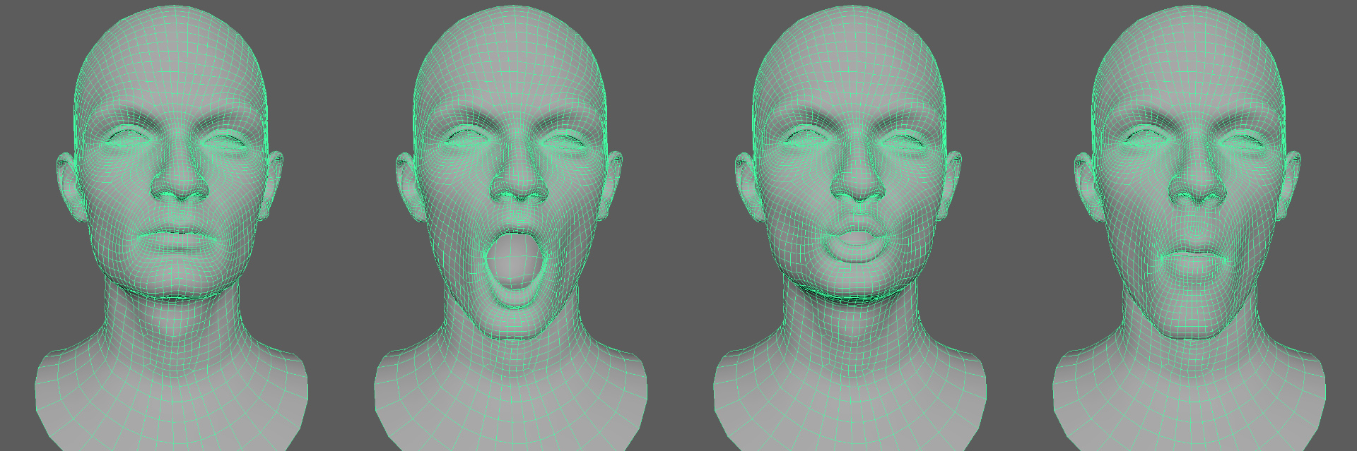
The hard part is creating a face rig to be driven by this animation data. In theory, the workflow is very simple. ARKit uses a set of 52 standard shapes, so all you have to do is author those blendshapes, hook up the weights, and then you’re done. The common approach is to scan an actor, clean the shapes, and you’re all set. For example, since ARKit has shapes for smile, frown, etc. you can scan those shapes, put them in a rig, and drive them with the blendshape animation. Apple documentation has a list of the shapes here: ARKit Blenshapes
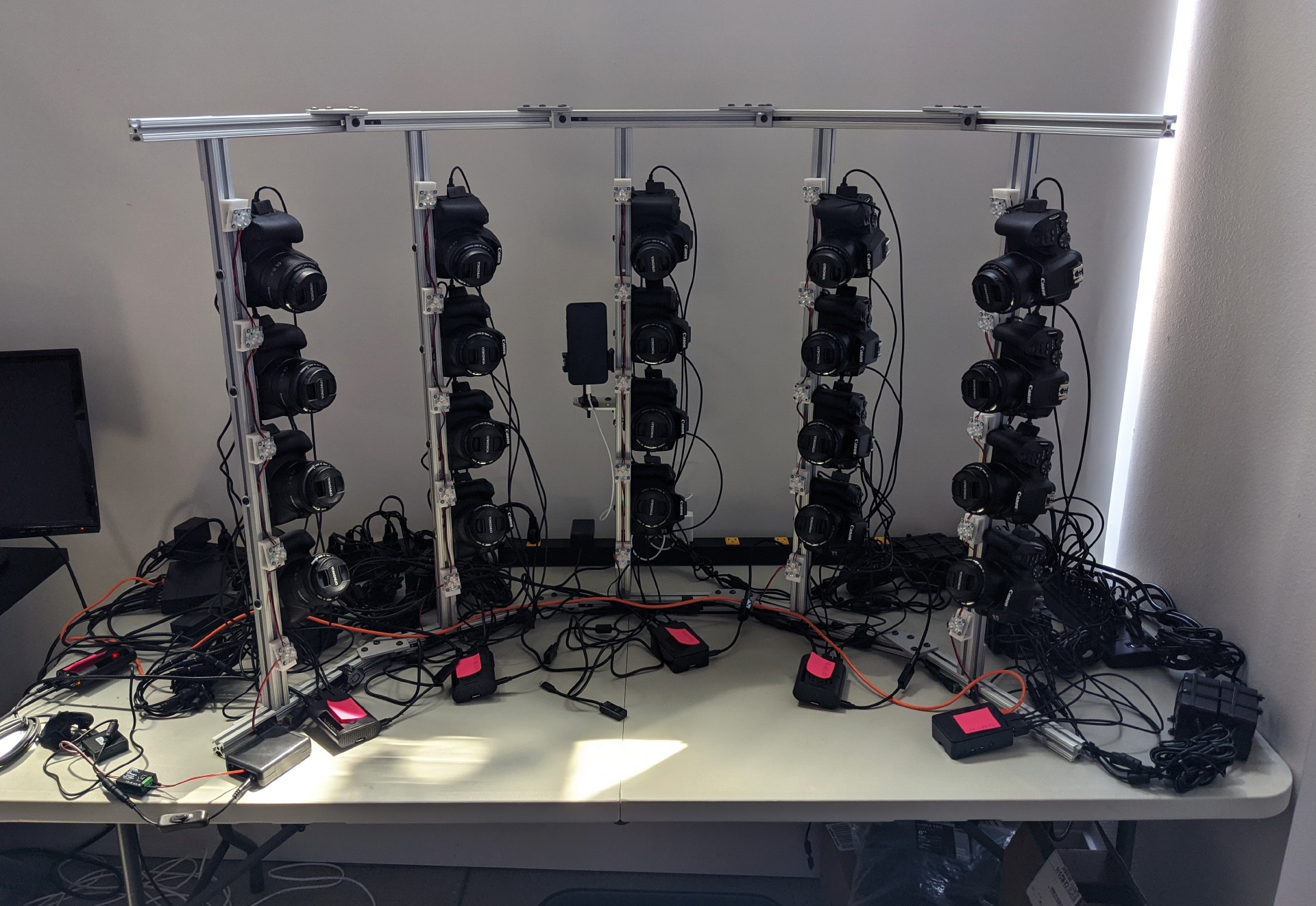
The problem is I’ve never managed to get good results out of it in the past. I tried FaceShift even back before they were purchased by Apple, but it never really worked for me. And even more concerning, I didn’t really understand why. To investigate this, I put together a photogrammetry setup in my apartment. Covid has made us all do strange things, and I built this scaning rig. My friends got a dog.
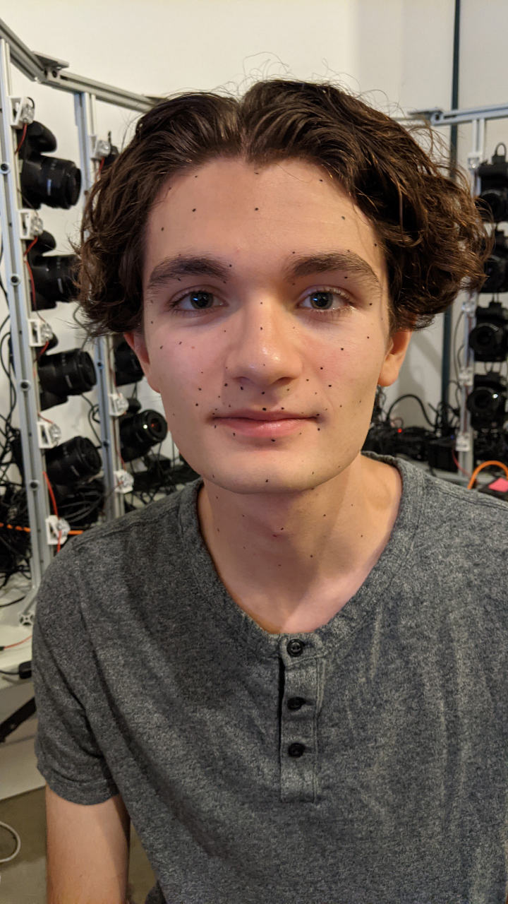
For this test, Colin Zargarpour graciously agreed to be the test subject. While I was putting this setup together, I asked Habib Zargarpour if he knew any actors/models who would be up for this, and he said “Well, my son Colin is in town for a few more days”. At the time, I was actually about a week away from being ready to shoot, so I said “sure, why not”. When has lack of preparation ever caused problems?
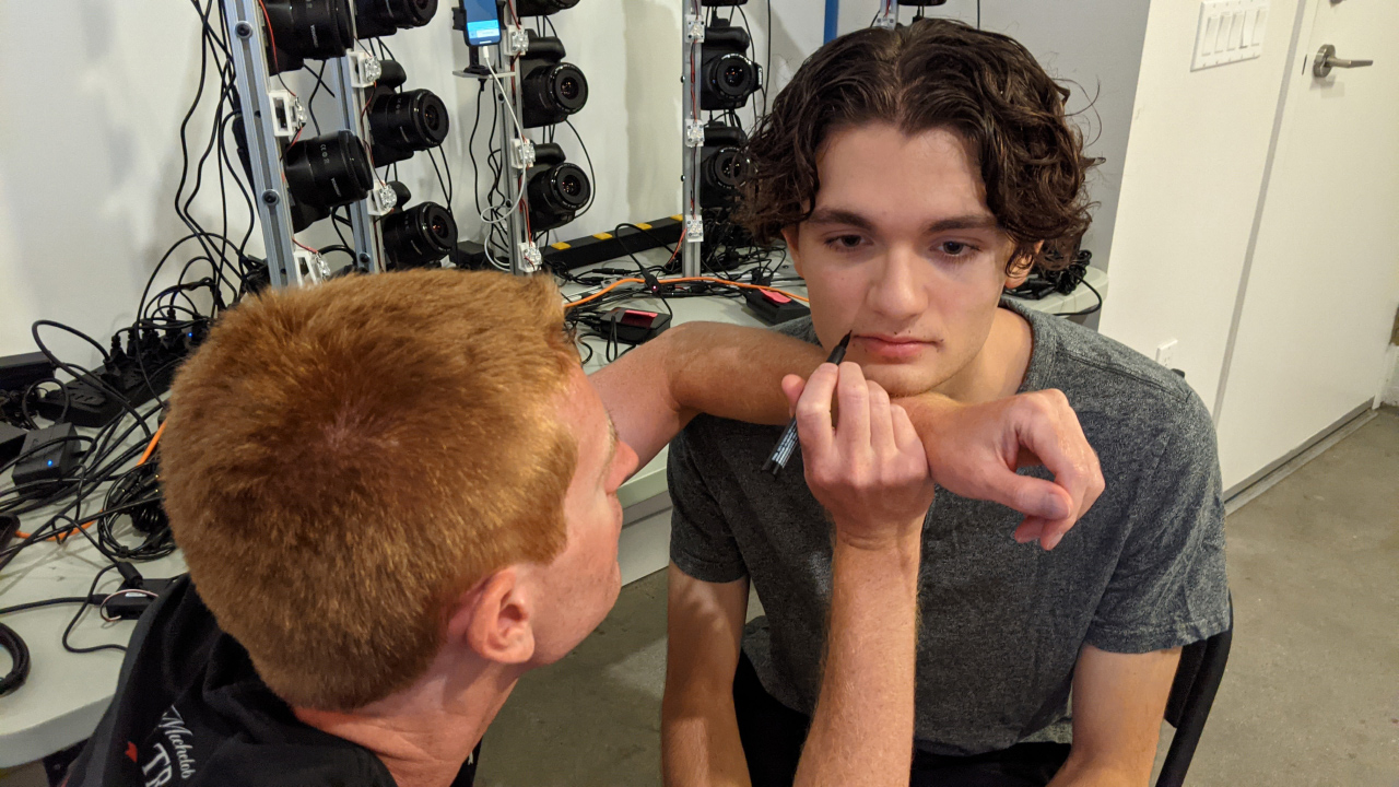
So we did the shoot, and we ran into a few issues, but got it done. I definitely owe Colin a beer for his patience with my very out-of-practice eyeliner skills.
The actual scan setup isn’t particularly interesting. I’m using 20x Rebel SL3s controlled by Raspberry PIs. Since I don’t have an extra room, it was a hard constraint that the entire setup must fit on a desk. In the past I have had photogrammetry setups scattered about my living room floor for months on end but…no, not doing that again. So while you would normally use 50mm fixed lenses, these cameras have 35mm fixed lenses to keep the setup compact.
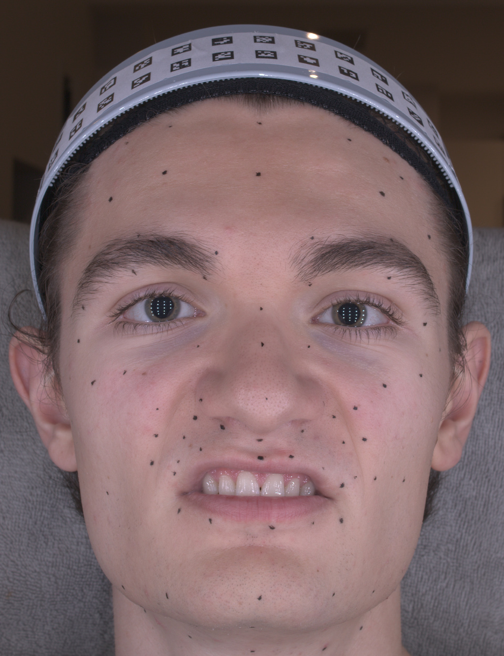
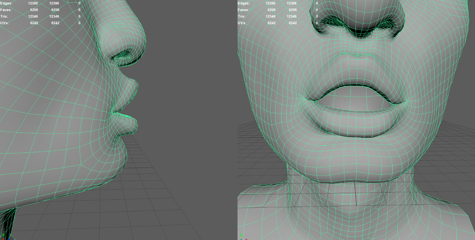
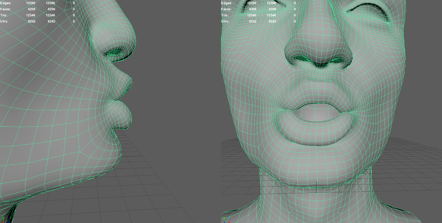
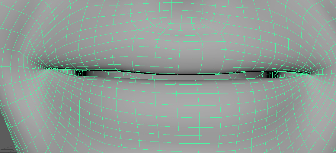
I’ve scanned quite a few shapes over the years, and tried to use ARKit (or FaceShift before they were purchased) several times, with different scans. Each time I try it…it looks terrible. The animation is unstable, jittery, and just looks awful. So, what am I missing? Turns out, a lot. After looking at the data, it started to make sense. Take a look at this shot, with Colin making a lip upper up expression. He is neutral, relaxed, but only moving up the upper lip.
ARKit has shapes specifically for this motion, mouthUpperUp_L and mouthUpperUp_R. So in theory, we should take this finished scan and split it into a left and right blendshape. Then we can do this for all the shapes in the blendshape list, and we should have a rig that can be effectively driven by ARKit. However, take a closer look at the scanning rig: You might have missed something.
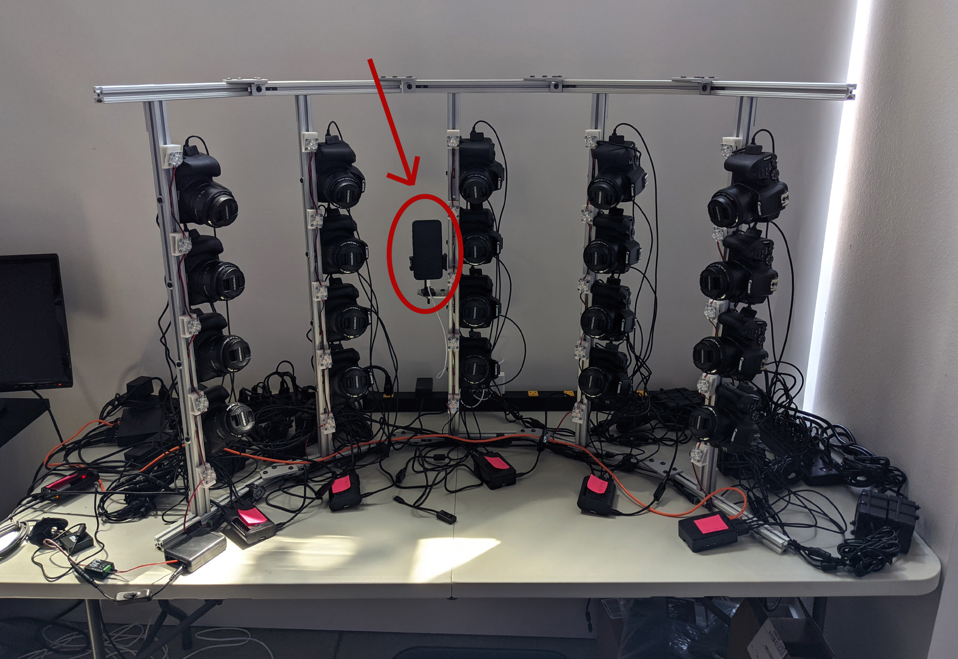
Yep, that’s an iPhone. During the shoot, the iPhone was streaming the live ARKit shapes (using FaceCap). Then right before each capture I recorded the ARKit weights so that I have a set of ARKit blendshape weights for every scan shot.
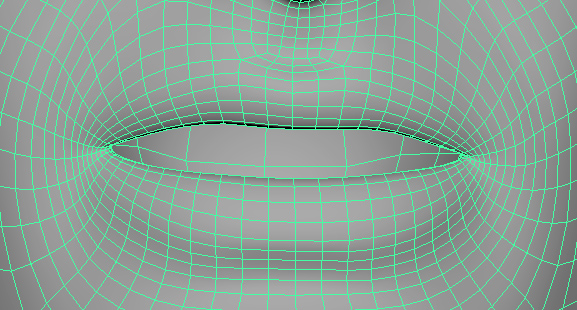
Looking at the reference, Colin is making a lip upper up. However, ARKit sees something different. Skipping ahead for a moment, the final ARKit shape looks like this:
ARKit does not see a single lip upper up shape. Rather, it only sees a 47.1% mouthUpperUp_L and a 49.7% mouthUpperUp_R. Those shapes look like this after processing.
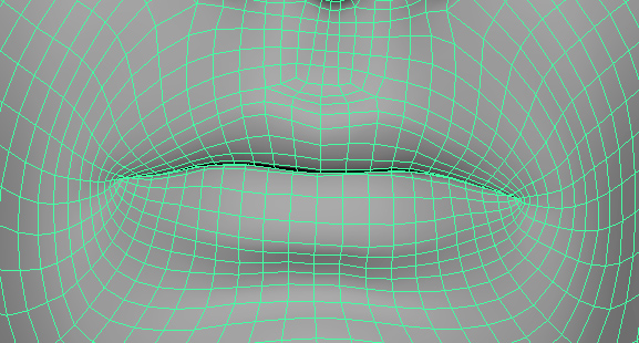
ARKit also finds a bunch of other small blendshapes. For example, it sees a 15.0% mouthFunnel, a 22.1% mouthSmile_R, and a 25.2% mouthLowerDown_L. All the extra shapes add up to this:
And for reference, here is the neutral:
ARKit under-the-hood has a very specific meaning for each of the shapes. The solver on the iPhone expects the combinations of shapes to work a certain way. And there are many circumstances where two shapes are activated in a way that counteract each other. ARKit uses combinations of these shapes to make meaningful movements to the rig, but if the small movements in your rig don’t match the small movements in the internal solver then the resulting animation falls apart. And that’s why my previous tests of ARKit failed…my blendshape rigs weren’t respecting the combinations of the underlying animation solver. If you take the entire scanned lip upper up and use that as your mouthUpperUp_L and mouthUpperUp_R blendshapes, then these shapes will contain a bunch of movement that ARKit doesn’t expect to be in those shapes. And that explains why I could never get good results.
To me, that is the most difficult part of working with ARKit shapes. If you create a custom shape set, and those shapes don’t counteract each other properly, you will end up with weird motions. So where is the list of all the dependencies between the shapes to ensure that an ARKit blendshape rig moves smoothly? Where is the guide that says “shape A should have as much upward movement as shape B, but it should move to the left 50% as much as shape C”. There isn’t one.
However, we do have indirect knowledge. We know what the base shapes should look like. And given an expression, we know what the weights are. So we can try to solve the underlying shapes indirectly. Rather than cleaning up the final blendshapes by hand, we can choose some constraints and find the best fit shapes that fit our constraints, and hopefully we end up with good results.
Data Processing
The actual scan capture is pretty standard. The images were processed to scans using a custom pipeline I threw together. I’ve found that if you have poorly captured data, then some programs work and others don’t. In particular, Photoscan is very good at salvaging poorly shot data, not that I would know from experience with my own shoots (cough). But if you have clean images with good sync and coverage, Photoscan, Capture Reality, and AliceVision will all do a great job. For this one, I actually used Colmap because of how well the command-line workflow integrates with custom C++ coding, but any program is fine.
For processing the scans, I use WrapX because WrapX is awesome. I put together some flows and contracted Centaur Digital to perform the actual alignment. I have a few custom steps involving C++ coding, like using the Aruco markers for the initial rigid alignment. But I’ve found the cheapest, easiest way to process scans in bulk is to essentially brute-force it with WrapX. After processing this data, I had a set of clean scans.
The ARKit Shape Solver
Since capturing the ARKit shapes directly isn’t practical, let’s instead write a solver. In this case, as input we have the 102 expressions. In the data set you can download, the file colin_proc_rig.fbx has the final cleaned up shapes from Centaur Digital. And we know how each expression maps to the 52 blendshape weights (which is in the json folder). Thus, we will find the 52 blendshapes that are the best fit for the 102 expressions.
To explain it better, let’s work in rounder numbers. Suppose we have 100 scanned expressions and 50 blendshapes to solve (instead of 102 and 52). Additionally, our topology has about 6,000 verts. How would we set up a solver to do it?
Since X, Y, and Z are independent, we can solve each channel individually. We have 6,000 verts in the base mesh, and a full ARKit rig needs 50 blendshapes. So we are essentially solving for a vector of 6,000 * 50 = 300,000 variables.
We need to describe our constraints as a single, large, sparse matrix. There are many approaches to do this, but I prefer to work with flat std::vectors.
std::vector < int > sparseR, sparseC;
std::vector < float > sparseV;
std::vector < float > sparseB;
We are trying to find the best fit solution for the over-constrained system of equations: Ax=b. The matrix A is sparse. For each nonzero element in the matrix A, sparseR is the row, sparseC is the col, and sparseV is the the value. On the right side, sparseB is just b. To construct the matrix, we can add matrix elements one at a time by using the SetSparse() helper function.
static void SetSparse(std::vector < int > & sparseR,
	std::vector < int > & sparseC,
	std::vector < float > & sparseV,
	int r, int c, float v)
{
	ASSERT_ALWAYS(sparseR.size() == sparseC.size());
	ASSERT_ALWAYS(sparseR.size() == sparseV.size());

	sparseR.push_back(r);
	sparseC.push_back(c);
	sparseV.push_back(v);
}
The Blendshape Constraint
Our first constraint is that for each of our 100 shapes, we know the blendshape weights. For every vertex in that shape, the sum of the known weights times the unknown shapes should equal the observed, scanned shape. We have 100 scanned shapes, and 6,000 verts, so we have a total of 600,000 constraints. I.e. we have 600,000 rows in our matrix for this constraint.
for (int poseIter = 0; poseIter < M; poseIter++)
{
  for (int vertIter = 0; vertIter < V; vertIter++)
  {
    for (int faceCapIter = 0; faceCapIter < N; faceCapIter++)
    {
      // at this pose, what is the expected weight for this shape
      float faceCapW = faceCapWeights[poseIter][faceCapIter];
      float faceCapVertW = capRigShapeInfl[faceCapIter][vertIter];

      if (faceCapW >= 1e-5f && faceCapVertW >= 1e-4f)
      {
        int col = faceCapIter * V + vertIter; // shape iter, then vert
        SetSparse(sparseR, sparseC, sparseV, currRow, col, faceCapW);
      }
    }

    Vec3 expectedP = fullShapeMesh.m_blendShapeData[poseIter][vertIter];
    Vec3 baseP = fullShapeMesh.m_posData[vertIter];
    Vec3 offsetP = expectedP - baseP;
    float val = ExtractVec3(offsetP, dim);
    sparseB.push_back(val);
    currRow++;
  }
}
On thing you will also notice is the faceCapVertW. The final blendshape should only affect the region touched by the initial blendshape. As a preprocess, a mask is created for each shape describing the region of influence. This way our eye shapes don’t have movement in the lips and vice-versa.
The Source Constraint
Additionally, we want to make sure that our blendshapes match the original shapes. We want our smile shape to roughly match the shape of the original ARKit smile shape, etc. So for this, we add a Source constraint. For each vertex in our original shape, we simply create an equation where the found shape matches the original shape. As we have 50 original shapes, and 6,000 verts, this constraint adds 300,000 rows to our matrix.
for (int faceCapIter = 0; faceCapIter < N; faceCapIter++)
{
  for (int vertIter = 0; vertIter < V; vertIter++)
  {
    Vec3 expectedP = capRigSrc.m_blendShapeData[faceCapIter][vertIter];
    Vec3 baseP = capRigSrc.m_posData[vertIter];
    Vec3 offsetP = expectedP - baseP;

    float val = ExtractVec3(offsetP, dim);

    int col = faceCapIter * V + vertIter;
    float mask = 1.0f;

    float faceCapVertW = capRigShapeInfl[faceCapIter][vertIter];

    float w = faceCapVertW;
    float scale = LerpFloat(10.0f, 1.0f, sqrtf(w));
    mask *= scale;

    SetSparse(sparseR, sparseC, sparseV, currRow, col, 1.0f * mask);

    sparseB.push_back(val*mask);
    currRow++;
  }
}
As a tweak, this constraint has a higher influence in areas that are outside the masked area of this shape. In theory we could make the constraint infinitely strong, but in practice large numbers start to make the solver unstable.
The Laplacian Constraint
In order to get good results, we actually need one more constraint. It’s important to ensure that the curvature of our source shapes roughly matches the curvature of our found shapes. And we can do this by constraining the laplacian.
In geometry, the laplacian is the offset of a vertex from the average of its neighbors.
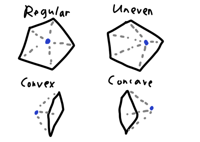
The laplacian contains quite a lot of information about a vertex. For example, if it is a regular pattern, the vertex will be near the average and the laplacian will be zero. However, most objects do not have evenly spaced edge loops, and the laplacian can encode this information. In another case, the neighbors form an approximate plane. If this vertex is in front of the plane, then the geometry is convex. Whereas if this vertex is behind the normal of the plane then this vertex is in a concavity. By ensuring that our resulting shapes have the same laplacian as our original shape, we can roughly match the original intention of the shape.
for (int faceCapIter = 0; faceCapIter < N; faceCapIter++)
{
  float laplWeight = 1.0f;
  for (int vertIter = 0; vertIter < V; vertIter++)
  {
    Vec3 poseLapl = capRigLapl[faceCapIter][vertIter];
    Vec3 baseLapl = neutralLapl[vertIter];

    Vec3 offsetLapl = poseLapl - baseLapl;

    int numAdj = adjData.m_vertSize[vertIter];
    ASSERT_ALWAYS(numAdj >= 1);

    float scale = SafeInv(float(numAdj));
    float expected = ExtractVec3(offsetLapl, dim);

    // the actual is the current point minus the average of the neighbors
    int start = adjData.m_vertStart[vertIter];
    int col = faceCapIter * V + vertIter;

    SetSparse(sparseR, sparseC, sparseV, currRow, col, laplWeight);

    float sumAvg = 0.0f;
    for (int i = 0; i < numAdj; i++)
    {
      int adjVert = adjData.m_vertData[start + i];
      int adjCol = faceCapIter * V + adjVert;

      SetSparse(sparseR, sparseC, sparseV, currRow, adjCol, (-1.0f) * laplWeight * scale);
    }

    sparseB.push_back(expected * laplWeight);
    currRow++;
  }
}
Finally, once this matrix built we simply solve it and use the result. startX is the initial guess. The sparse parameters are described above. numRows and numCols are the dimension of matrix A. And 1000 is the maximum iteration count, although it tends to converge in about 50. The solver is quite fast (only a few seconds) so I didn’t bother with optimizing it.
LinearAlgebraUtil::SolveConjuateGradientSparseLeastSquares(startX, sparseR, sparseC, sparseV, sparseB, numRows, numCols, 1000);Results
That’s really it. What does it look like? Overall, I was pleasantly surprised.
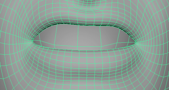
Here is the original lip funnel expression, made by the simply adding the offsets from the original ARKit shape to the Colin neutral scan.
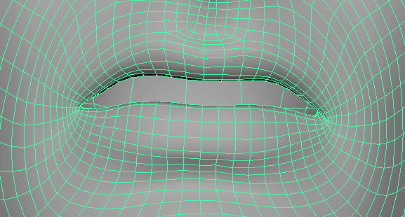
It looks pretty rough. The lower lip is very thin. But applying the solver results in this shape for the lip funnel.
The solved expression are pretty clean. The expression matches the reference, and the lips seems to keep their volume. What I really like about this approach is that the combinations “just work”. By running a solver on a dense data set, we end up with shapes that work well together. In particular, I’ve always had trouble making lip shapes (like funnel, etc) work well with a jaw down expression.
If I had more time, the next step would be to tweak the solver for the lips and eyelids to close. In a few cases, shapes that should be closed ended up slightly open. For example, the smile opens the lips when it really should not.
There are several ways to do this while still using a linear solver. For each point on the lower lip, we could find a nearby point on the upper lip and add a constraint for certain poses that the distance between those points shouldn’t change for the Y component. I would expect this to work quite well, but have not had time to test.
I’m going to skip a long discussion of all the shapes, since the best way to evaluate the results is to actually look at the results. Since the data is included in the link below, feel free to look at it yourself. But here are my main conclusions:
What worked well:
- The shapes "just worked". I was expecting to need manual cleanup for the eyes/eyelids, but the results were clean with minimal tweaking.
- The combinations add together well. In the past I've ended up in the quagmire of trying to get all the jaw and lip combinations to add well together. It turns into a delicate pile of sand where tweaking one shape breaks another. It's much easier to just throw it into a solver.
- The workflow is non-destructive. If one of the source shapes needs a revision, you can change it, press a button, and the whole rig rebuilds.
- Shooting and rigging is easier. Since we don't care about capturing an exact shape, the actual shoot goes very quickly. We don't need to make sure the talent is activating the perfect combination of shapes. As long as we are capturing enough range of motion, then we have enough data for the solver. Then for processing, we just have to clean up the shapes to match the scan. We don't need 10 sculpting revisions of the lower lip because something in the animation looks off.
- The solver acts as a soft denoise for the shapes. If you look closely, the processed shapes could be improved with a few more revisions. The neck has extra movement, some of the lip contours are bit off...that kind of thing. However, the solver removes those uncorrelated movements so we don't actually need to fix them.
What did not go so well:
- The main disadvantage is that we lose quite a bit of detail in the shapes. The hand-wrapped shapes have details in the lips which are lost in the conversion to ARKit shapes.
- The lips and eyelids opening/closing would definitely need to be fixed before using a technique like this in a real production.
- When you apply a solver, "you get what you get". However, if your animation directory doesn't like the shape of the lip, there really isn't much you can do, which is both a blessing and a curse. If you want manual changes, there might be ways to do it. For example, if you need to change the lower lip in the dimpler, you could sculpt it by hand and add a constraint to the solver. But if you apply too many manual changes it defeats the purpose of having a solver in the first place.
- We capture more shapes that we actually use. In this case, 100 shapes were processed to create only 50 final blendshapes. And it's really only about 30 blendshapes if you merge the left and right variations. If I were to optimize this capture process, I think I could reduce the set to about 60 and keep the same quality, but that wasn't tested. In particular, I find it essential to capture jaw-down and jaw-neutral variations of the lip movements, but some of those could be removed if cost is a factor. And cost is always a factor.
Data:
You can download the data set here. It’s available on a CC0 license, so feel free to look at it and use it however you like. colin_shape_data.zip
Anyways, that’s what I got. Feel free to look at the data, and I hope it’s useful to you.
Acknowledgments:
Scan Talent: Colin Zargarpour
Executive Producer: Habib Zargarpour
Scan Manual Cleanup: Centaur Digital (www.centaurdigital.com)
Source Animation: Bannanaflak, the makers of FaceCap. Source recording from their site: FaceCap_ExampleRecording.rar